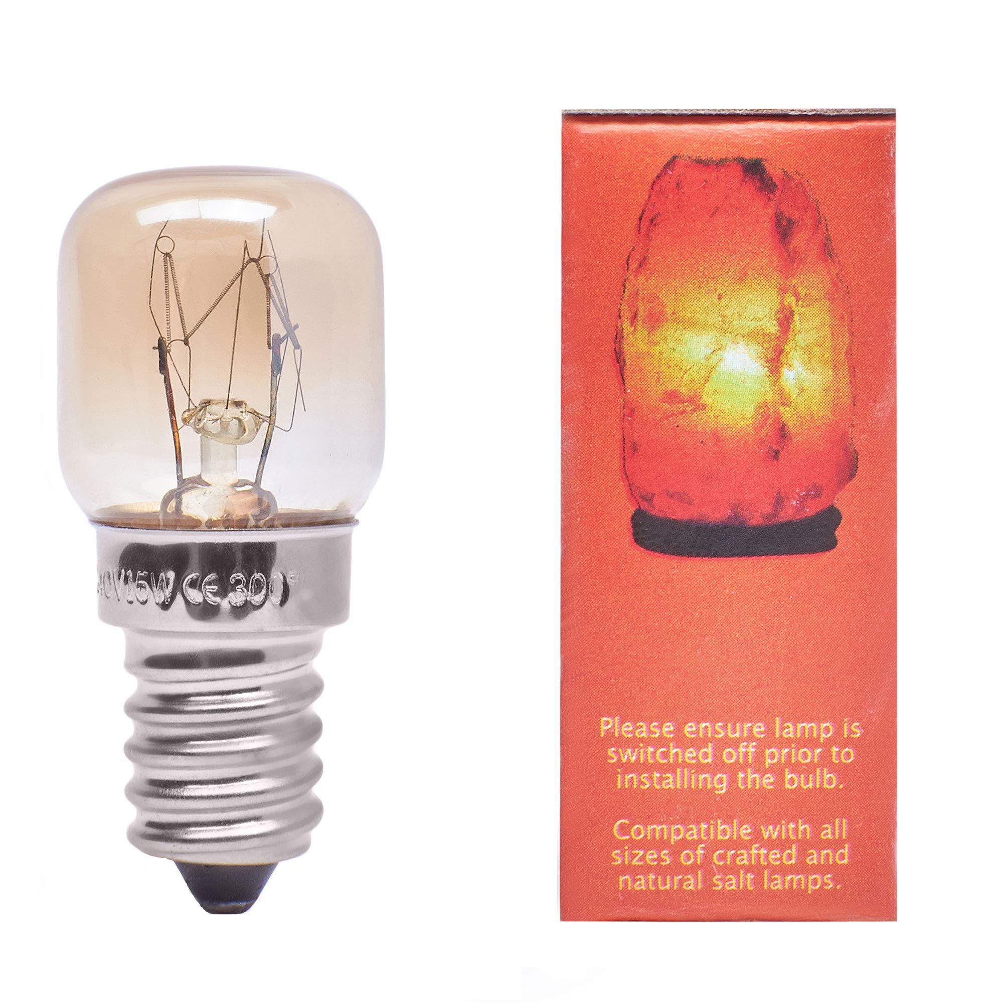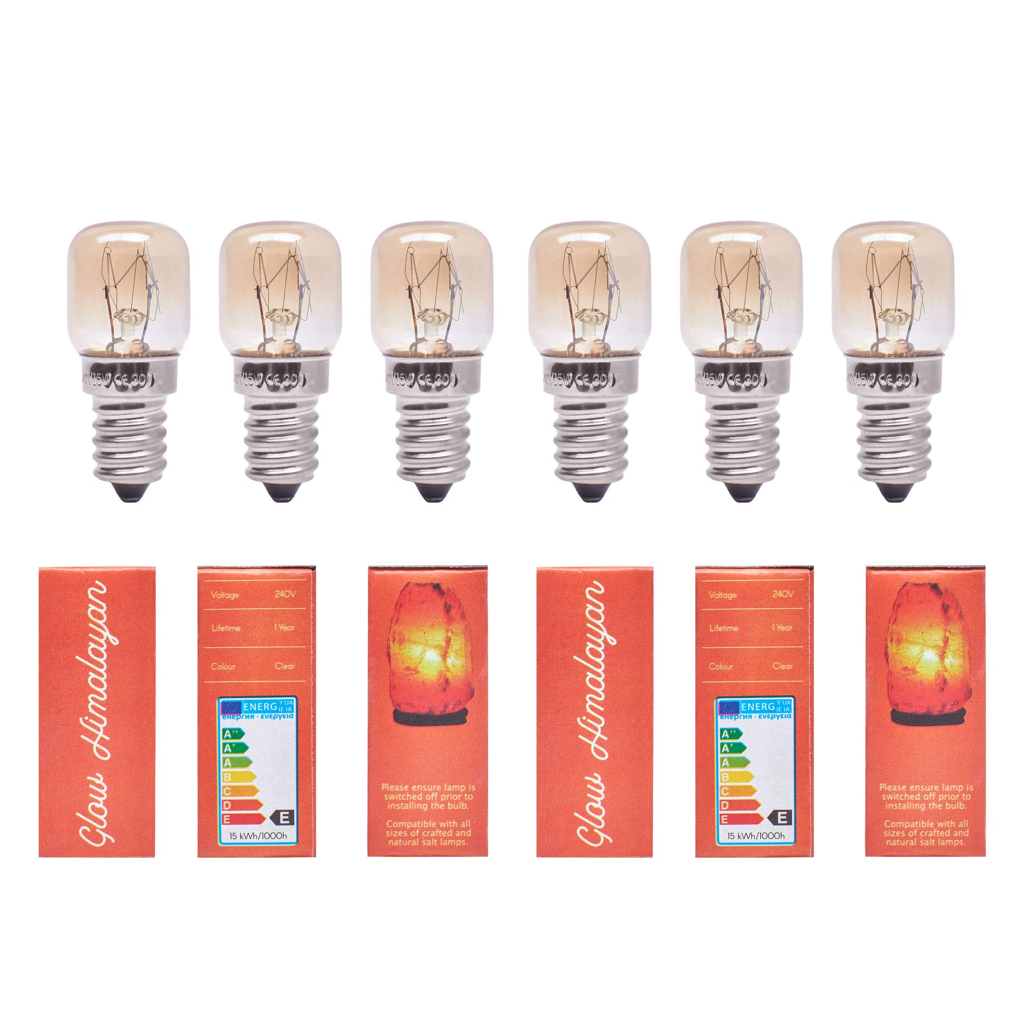
Glow Himalayan
⏳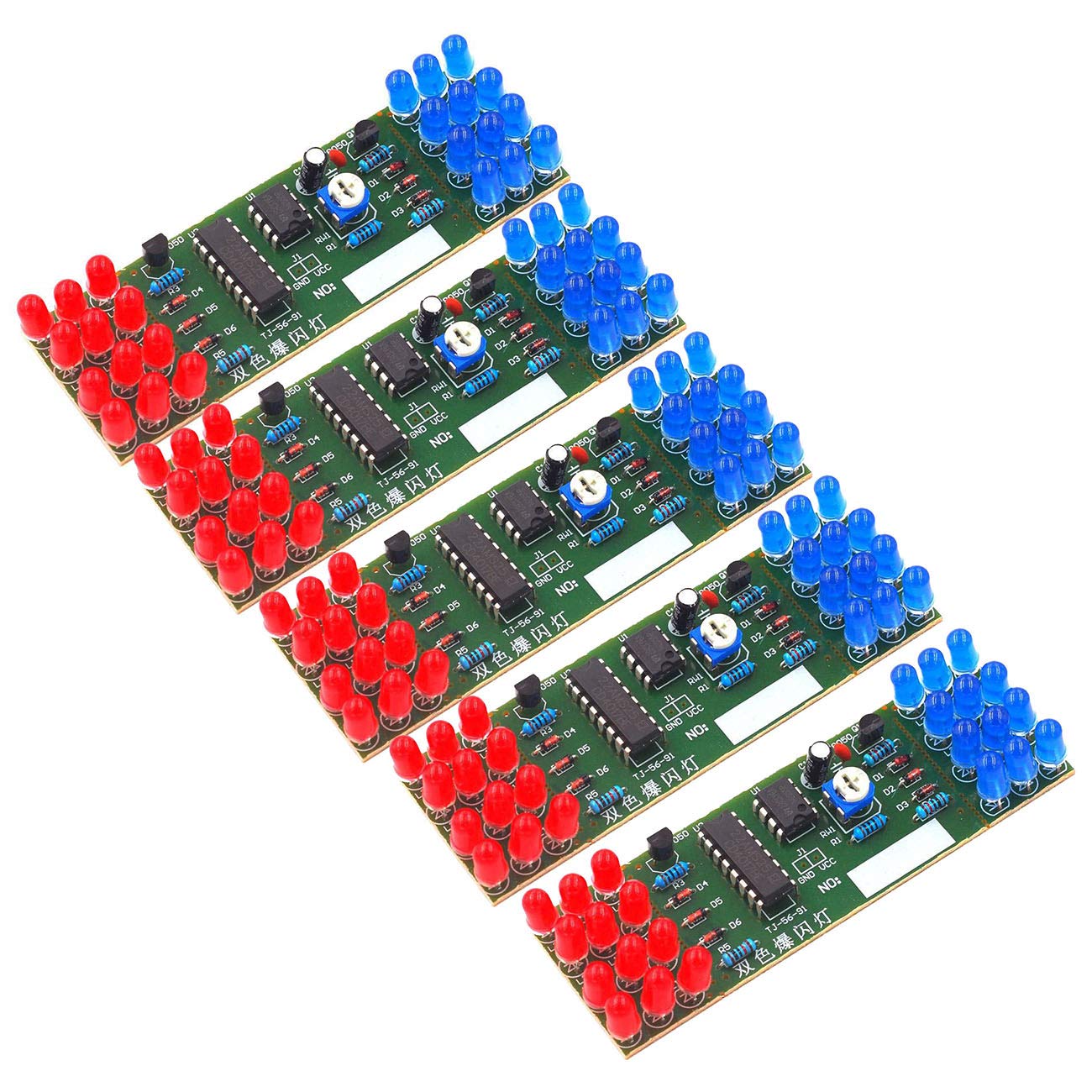
1. This suite adopts simulation light circuit made with NE555 and CD4017, the blue LED and red LED flashed alternately according to the pulse. 2. The multivibrator composed of NE555 will have a certain frequency of oscillation signal send to CD4017 decimal counter/pulse distributor, in order to count. 3. When the 1, 3, 5 pulses arrive Q0, Q2, Q4 output high level in turn, blue LED flashes 3 times, Q5, Q7, Q9 output high level in turn. 4. Red LED flashes 3 times, blue LED flashes again when 11, 13, 15 pulses come, blue and red LED flashes alternately circulatory, so as to like the alarm lamp.Change the RP1 size can change the oscillation period, thus changing the LED shining speed, the whole circuit DC9-12V can be worked. 5. Red flashing light and blue flashing light form a board separately, connected with the main board through the stamp hole. 6. If you need to install to other place separately or increase the distance, you should cut off through the stamp hole, then connect with the mother board by two wires. 7. Please pay attention to the direction of LED when installing, especially the direction of L11 and L12. 8. The R2 and R3 controls with the brightness of light, you can change it appropriately , the range is 10-100 ohm. Installation note: The kit uses red and blue light-emitting diodes. The blue LED has a higher turn-on voltage than the red LED. Therefore, the red LEDs are connected in series of four, and the blue LEDs are connected in series of three. Pay attention to this first. If the color is reversed, a higher voltage is required to light up. Package Including: 5 * NE555 CD4017 LED Electronic
Customer reviews
10 Trustpilot reviews total, with 2 shown at a time.
I wrote to Bigamart's customer support and they accompanied the process of reshipping the item until it finally arrived. I felt a genuine effort to solve the problem till it was finally solved.
The package was here in Australia from England in a few days — so quick! Something was missing and they refunded it straight away. Pretty happy with these guys.
You might also like